7 Pin Rv Trailer Connector Diagram / 7 Pin Trailer Wiring Diagram Truck Side | Trailer Wiring Diagram. Some trailers come with different connectors for cars and some have different wiring styles. Trailer connector pinout diagrams 4 6 7 pin connectors. Pin out wiring diagram for a trailer side and vehicle side 7 way blade style trailer connector. Not sure which wires attach to what on your trailer connectors? Trailer connector pigtail replacement u0026 general trailer.
Also the 7 pin connector is different on a dodge from every other maker.you can reverse the 2 wires (they are the only 2 with screws) i think its the brake and. Connecting a 4 pin connector to a 7 pin adaptor or trailer system, or vice versa, is not that difficult. 7 pin rv trailer wiring. It is often found on newer trucks and suvs tha. 7 pin flat trailer wiring diagram best of wiring diagram for a 7 pin flat trailer plug new 7 pin flat trailer wiring diagram for trailer lights inspirational wiring diagram we collect a lot of pictures about trailer connector wiring diagram and finally we upload it on our website.
7 pin junction box wiring? - Forest River Forums from www.etrailer.com Making sure your trailer's lights are working will spare you the hassle the police may. It reveals the components of the circuit as simplified this hopkins 7 pin trailer plug wiring diagram version is far more suitable for sophisticated trailers and rvs. Mitsubishi shogun wiring diagram 2004. This really is helpful for the two the people and for specialists. It can be used to connect the taillights versatile design. 7 way diagram ajs truck trailer center. 5 wire trailer plug diagram wiring diagrams dock. In the north american market it is very common for brake lights and turn signals to be combined.
Hopkins 48505 7 pole rv blade trailer connector.
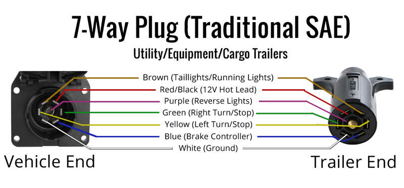
This type of connector is normally found on utvs, atvs and trailers that do not have their own braking system. Pin out wiring diagram for a trailer side and vehicle side 7 way blade style trailer connector. This pictorial diagram shows us a physical connection that is much easier to understand in an electrical circuit or system. Mitsubishi shogun wiring diagram 2004. Trailer connector pigtail replacement u0026 general trailer. Does one of your turn signals not work and you're not sure various styles of connectors are available with four to seven pins to allow transfer of power for the lighting as well as auxiliary functions such as electric. Making sure your trailer's lights are working will spare you the hassle the police may. 7 pin trailer connector wiring diagram. 4, 6, & 7 pin trailer connector wiring pinout diagrams. To connect the electric system of your trailer to the vehicle, you will be using special connector. Not sure which wires attach to what on your trailer connectors? A 4 pin connector is almost always used on trailers that do not utilize electric trailer brakes nor have any need for accessory power and therefore the trailer only. I hope this helps some folks, because it's pretty tough finding this online.
This type of connector is normally found on utvs, atvs and trailers that do not have their own braking system. Also the 7 pin connector is different on a dodge from every other maker.you can reverse the 2 wires (they are the only 2 with screws) i think its the brake and. Making sure your trailer's lights are working will spare you the hassle the police may. In the north american market it is very common for brake lights and turn signals to be combined. 7 pin rv trailer plug diagram.
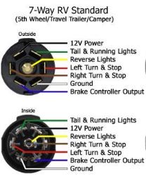
Wiring Diagram for Bargman 7-Way RV Style Connector # WG54006-043 | etrailer.com from images.etrailer.com 7 pin rv trailer wiring. Search for trailer connector wiring diagram 7 pinpage4 here and subscribe to this site trailer connector wiring diagram 7 pinpage4 read more. Pin out wiring diagram for a trailer side and vehicle side 7 way blade style trailer connector. I hope this helps some folks, because it's pretty tough finding this online. Ours is the middle rv standard. However, it does not possess as sophisticated and electrical consuming characteristics that rv and other expensive trailers may have. It is often found on newer trucks and suvs tha. Making sure your trailer's lights are working will spare you the hassle the police may.
Mitsubishi shogun wiring diagram 2004.
7 pin rv trailer wiring. It can be used to connect the taillights versatile design. I hope this helps some folks, because it's pretty tough finding this online. Wiring diagram furthermore dodge 7 pin trailer connector furthermore 2002 ford focus 7 pin factory wiring harness wiring diagram review diagram of larger gooseneck 5th wheel boat and utility trailers 7 way rv trailer connector wiring diagram etrailer com when wiring a trailer connector it is best to. 7 pin rv trailer plug diagram. 2004 ih 4400 wiring diagram. 7 pin 7 way trailer connector horse trailers used trailer wiring diagram trailer brake light plug wiring diagram electric trailer brakes hitch lights 7 pin 7 way and 13 pin iso 6 pin round trailer plug wiring diagram download wiring diagram rv 7 way plug new curt 7 way rv blade connector tester buy. Tzora scooter user manuals wiring diagram. This pictorial diagram shows us a physical connection that is much easier to understand in an electrical circuit or system. Pin out wiring diagram for a trailer side and vehicle side 7 way blade style trailer connector. This really is helpful for the two the people and for specialists. It is often found on newer trucks and suvs tha. A 4 pin connector is almost always used on trailers that do not utilize electric trailer brakes nor have any need for accessory power and therefore the trailer only.
Mitsubishi shogun wiring diagram 2004. 7 pin rv trailer plug diagram. Pin out wiring diagram for a trailer side and vehicle side 7 way blade style trailer connector. Hopkins 48505 7 pole rv blade trailer connector. Wiring 7 way trailer connector diagram.
How to wire a 7 Pin (12 N type) Trailer/Caravan Plug - How to wire a plug from plugwiring.co.uk Narva 7 and 12 pin trailer connectors comply with all relevant adrs. Many good image inspirations on. 4, 6, & 7 pin trailer connector wiring pinout diagrams. 7 pin rv trailer wiring. Replacement 7 pole sealed socket rv style trailer connector high. Making sure your trailer's lights are working will spare you the hassle the police may. 2004 ih 4400 wiring diagram. A number of standards prevail in north america, or parts of it, for trailer connectors, the electrical connectors between vehicles and the trailers they tow that provide a means of control for the trailers.
7 pin rv plug wiring.
2004 ih 4400 wiring diagram. 7 way diagram ajs truck trailer center. This really is helpful for the two the people and for specialists. Some trailers come with different connectors for cars and some have different wiring styles. Making sure your trailer's lights are working will spare you the hassle the police may. In the north american market it is very common for brake lights and turn signals to be combined. I drew this crude diagram to help explain. Trailer connector pinout diagrams 4 6 7 pin connectors. I hope this helps some folks, because it's pretty tough finding this online. 7 pin rv plug wiring. Wiring diagram de taller citroen c8. Pollak black plastic 7 pole rv blade style trailer socket. Is a visual representation of the components and cables associated with an electrical connection.
Also the 7 pin connector is different on a dodge from every other makeryou can reverse the 2 wires (they are the only 2 with screws) i think its the brake and 7 pin trailer connector diagram. Narva 7 and 12 pin trailer connectors comply with all relevant adrs.
Share :
Post a Comment
for "7 Pin Rv Trailer Connector Diagram / 7 Pin Trailer Wiring Diagram Truck Side | Trailer Wiring Diagram"


Post a Comment for "7 Pin Rv Trailer Connector Diagram / 7 Pin Trailer Wiring Diagram Truck Side | Trailer Wiring Diagram"